Relays are essential components in electrical systems, but understanding how they work can feel overwhelming. With this simple guide, we’ll break down the basics of relay wiring using a helpful diagram to explain how they function, the role of their pins, and how to connect them to your setup.
Understanding Relay Wiring: A Step-by-Step Guide
Relays are essential components in electrical systems, but understanding how they work can feel overwhelming. With this simple guide, we’ll break down the basics of relay wiring using a helpful diagram to explain how they function, the role of their pins, and how to connect them to your setup.
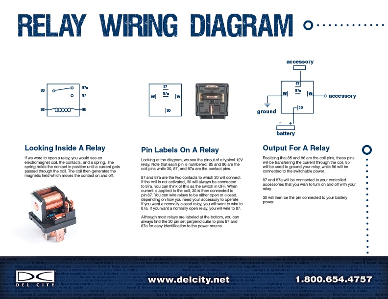
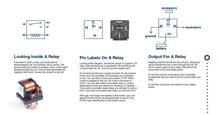
Looking Inside a Relay
If you were to open a relay, you’d find three key components:
- Electromagnetic Coil: Generates a magnetic field when current passes through it.
- Contacts: Connects or disconnects the circuit depending on the relay’s state.
- Spring: Holds the contacts in their default position (either Normally Open or Normally Closed).
When the coil is energized, the magnetic field moves the contact, switching the circuit on or off.
Pin Labels on a Relay
Relays have standardized pin labels, making it easier to wire them correctly. Let’s take a closer look at the typical 12V relay shown in the diagram:
- 85 & 86: The coil pins. These are used to power the electromagnetic coil.
- 30: The common terminal, which serves as the input for power from the battery.
- 87 & 87a: The output terminals.
- 87: Connected when the relay is energized (Normally Open).
- 87a: Connected when the relay is not energized (Normally Closed).
The pin layout ensures you can always find pin 30 perpendicular to 87 and 87a, helping you identify the power source and output terminals.
How to Wire a Relay
The wiring process becomes straightforward when you understand the pin functions:
- Connect the Power Source:
- Attach pin 30 to the positive terminal of your battery.
- Control the Coil:
- Use pins 85 and 86 to power the electromagnetic coil. One pin connects to ground, and the other connects to the switch or control mechanism.
- Route the Output:
- If your relay is Normally Open, connect the output to pin 87. The circuit will activate when the relay is energized.
- If it’s Normally Closed, use pin 87a to maintain a closed circuit when the relay is deactivated.
Relay Output
When the relay is activated, pins 85 and 86 energize the coil. This causes:
- The connection to switch from 87a (Normally Closed) to 87 (Normally Open).
- Power to flow from pin 30 to pin 87, sending energy to your connected accessories or devices.
Pin 30 remains the constant power input from the battery, while 87 or 87a determines where the power flows based on the relay’s state.
Why Use Relays?
Relays are indispensable in electrical circuits because they:
- Control High Currents: Relays allow low-current circuits to safely control high-current devices.
- Protect Components: By managing voltage and current flow, relays prevent damage to sensitive equipment.
- Add Functionality: They enable advanced features like timing delays, latching, and switching between circuits.
Keep This Diagram Handy
This relay wiring diagram is your go-to reference for understanding how relays work and how to wire them effectively. By familiarizing yourself with the pin layout and functionality, you’ll confidently integrate relays into your electrical projects.
Need more guidance or want to explore Del City’s relay offerings? Visit www.delcity.net or call us at 1.800.654.4757 for expert advice!